受力分析图:斜面上的物块
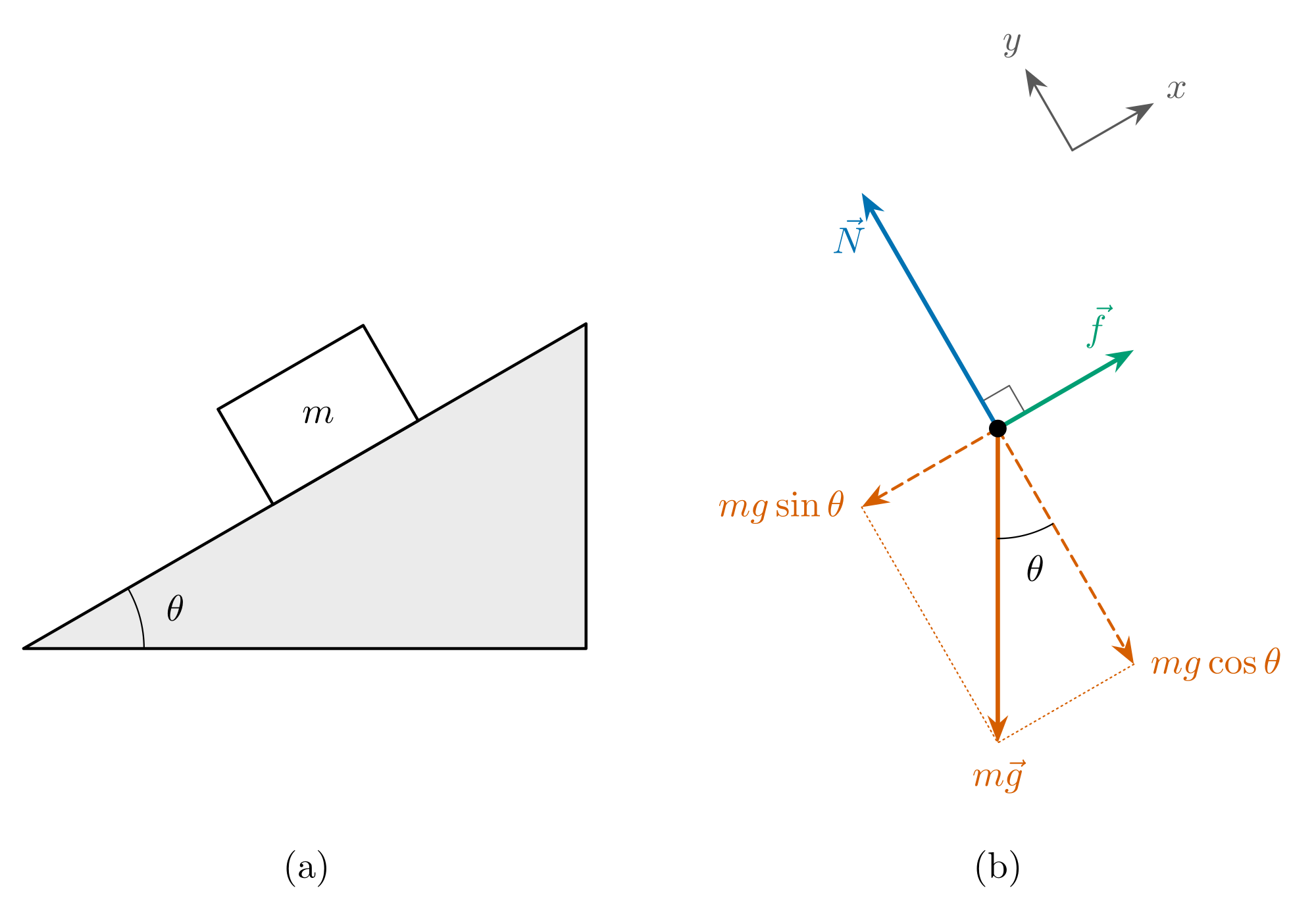
受力分析图只画一个物体本身,把作用在它上面的每一个力都画成从同一点出发的箭头。这里的物体是静止在粗糙斜面上的物块。图 (a) 是实际情景,图 (b) 是它的受力分析图:物块变成了一个点,斜面被去掉,只剩下三个力。
箭头按 30° 斜面的比例绘制,因此它们的长度可以相互比较,而且合力为零,对没有加速度的物块来说必须如此。切换到空白版可以练习标注,也可以拿下方的 TikZ 代码改一改倾角。
各部分及其含义
| 部分 | 表示什么 |
|---|---|
| 重力 mg | 地球对物块的引力。不管斜面多陡,它总是竖直向下。 |
| 支持力 N | 斜面对物块的支持作用,方向垂直于斜面。这里 N = mg cos θ。 |
| 摩擦力 f | 沿接触面,与物块将要滑动的方向相反,因此沿斜面向上。物块静止,所以这是静摩擦力,f = mg sin θ。 |
| mg sin θ | 重力沿斜面方向的分量。摩擦力必须与它平衡。 |
| mg cos θ | 重力垂直压向斜面的分量。支持力与它平衡。 |
| 角 θ | 斜面的倾角。它还出现在第二处:重力与斜面垂线之间的夹角。 |
| 坐标轴 | x 轴沿斜面,y 轴垂直于斜面。这样倾斜坐标轴后,只需要分解一个力。 |
把这张图看成两个平衡关系
物块静止,所以各力在每个坐标轴方向上分别平衡。沿斜面方向:f − mg sin θ = 0,所以 f = mg sin θ。垂直于斜面方向:N − mg cos θ = 0,所以 N = mg cos θ。这就是本题中牛顿第二定律的全部内容,可以直接从图上读出来。
虚线箭头不是额外的力。它们就是重力本身,只是重新画成了沿两个坐标轴的两个分量。要么算重力,要么算它的两个分量,绝不能两者都算。
斜面越陡,mg sin θ 越大,mg cos θ 越小。当 mg sin θ 超过静摩擦力所能提供的最大值 μN 时,物块开始下滑。这发生在 tan θ 大于静摩擦因数 μ 的时候。
受力分析图上不画的内容
- 物块对其他物体施加的力。物块压着斜面,但这个力作用在斜面上,所以应该画在斜面的受力分析图上。
- 速度和加速度。从这个点出发只画力。如果想表示加速度,请把它画在图的旁边。
- 合力的箭头,或者 ma。合力是已经画出的各个箭头之和,而不是另外再加的一个力。
- 每个力作用在物块的哪个位置。只要物块不翻倒、不转动,用一个点表示就够了;要分析翻倒或转动,就需要真实的作用点。
- 其他情形。没有摩擦时就没有 f。如果物块向下滑,摩擦力是滑动摩擦力,方向仍沿斜面向上。如果物块被推着沿斜面向上运动,摩擦力就沿斜面向下。
TikZ 代码
这是上面这张图的完整源代码。无需修改即可用 pdflatex 编译,在 LatexNotes、Overleaf 或你自己的电脑上都可以。
% Free-body diagram of a block at rest on a rough incline: (a) the situation, (b) the forces on the block.
% The forces are drawn to scale, so they add up to zero. Compiles as it is with pdflatex.
% Free to use and change: latexnotes.tech/diagrams/free-body-diagram
\documentclass[tikz,border=6pt]{standalone}
\usepackage{amsmath}
\usetikzlibrary{arrows.meta}

\definecolor{normal}{HTML}{0072B2}    % the normal force
\definecolor{friction}{HTML}{009E73}  % friction
\definecolor{weight}{HTML}{D55E00}    % the weight and its two parts

\newif\iflabels
\labelstrue   % write \labelsfalse here for the blank version to fill in

\newcommand{\slope}{30}   % the angle of the incline, in degrees
\newcommand{\W}{3}        % the length drawn for the weight mg, in cm

\begin{document}
\begin{tikzpicture}[>={Stealth[length=2.6mm]}, line cap=round, line join=round,
    force/.style={->, very thick}, part/.style={->, thick, densely dashed}]
  \pgfmathsetmacro{\N}{\W*cos(\slope)}   % normal force = mg cos(theta)
  \pgfmathsetmacro{\f}{\W*sin(\slope)}   % friction     = mg sin(theta)

  % (a) The situation: a block of mass m at rest on an incline at angle theta (its sloping side is 6.2 cm long)
  \begin{scope}[shift={(0,-1.75)}]
    \filldraw[thick, fill=black!8] (0,0) -- ({6.2*cos(\slope)},0) -- (\slope:6.2) -- cycle;
    \draw (1.15,0) arc (0:\slope:1.15);
    \begin{scope}[rotate=\slope]
      \filldraw[thick, fill=white] (2.75,0) rectangle (4.35,1.05);
      \iflabels \node at (3.55,0.525) {$m$}; \fi
    \end{scope}
    \iflabels \node at ({\slope/2}:1.5) {$\theta$}; \fi
  \end{scope}

  % (b) The free-body diagram: the block as a dot, and every force on it
  \begin{scope}[shift={(9.3,0.35)}]
    % The axes, drawn apart in the gap between the normal force and friction: x along the incline, y across it
    \begin{scope}[shift={(\slope+45:2.75)}, black!65]
      \draw[->, semithick] (0,0) -- (\slope:0.9);
      \draw[->, semithick] (0,0) -- (\slope+90:0.9);
      \iflabels
        \node at (\slope:1.15) {$x$};
        \node at (\slope+90:1.15) {$y$};
      \fi
    \end{scope}
    % The normal force is at right angles to the surface, and so to friction
    \draw[thin, black!65] (\slope:0.3) -- ++(\slope+90:0.3) -- (\slope+90:0.3);
    % The weight, straight down, and its parts along and across the incline
    \draw[weight, thin, densely dotted] (\slope+180:\f) -- (0,-\W) -- (\slope-90:\N);
    \draw[part, weight] (0,0) -- (\slope+180:\f);
    \draw[part, weight] (0,0) -- (\slope-90:\N);
    \draw[force, weight] (0,0) -- (0,-\W);
    % The normal force, away from the surface, and friction, up the incline
    \draw[force, normal] (0,0) -- (\slope+90:\N);
    \draw[force, friction] (0,0) -- (\slope:\f);
    % The incline's angle appears again between the weight and the line across the incline
    \draw (0,-1.05) arc (270:{270+\slope}:1.05);
    \fill (0,0) circle (2.4pt);
    \iflabels
      \node[normal, left=2pt] at (\slope+90:{0.82*\N}) {$\vec{N}$};
      \node[friction, above=3pt] at (\slope:{0.72*\f}) {$\vec{f}$};
      \node[weight, below=1pt] at (0,-\W) {$m\vec{g}$};
      \node[weight, left=1pt] at (\slope+180:\f) {$mg\sin\theta$};
      \node[weight, right=1pt] at (\slope-90:\N) {$mg\cos\theta$};
      \node at ({270+\slope/2}:1.38) {$\theta$};
    \fi
  \end{scope}

  \node at (2.7,-3.85) {(a)};
  \node at (9.3,-3.85) {(b)};
\end{tikzpicture}
\end{document}
\slope是斜面的倾角(单位为度)。修改它,两幅图都会随之变化:斜面、箭头和重力的两个分量。\W是重力箭头的绘制长度。支持力和摩擦力由它计算得出,所以箭头始终符合比例。- 要得到空白版,把
\labelstrue改成\labelsfalse。 - 对于光滑斜面,删掉摩擦力的箭头及其标注。这时物块会沿斜面加速下滑。
自己手绘了一张图?
LatexNotes 能把手写笔记的照片转换成 LaTeX,并把手绘的图形和图解重绘为可编辑的 TikZ 和 pgfplots,就像上面的代码一样。
常见问题
为什么重力与 y 轴之间的夹角也是 θ?
重力垂直于地面,y 轴垂直于斜面。把两条直线都转过同样的 90°,它们之间的夹角不变,所以重力与 y 轴的夹角等于地面与斜面的夹角。
支持力总是等于 mg 吗?
不是。只有在水平面上且没有其他竖直方向的力时,它才等于 mg。在斜面上它是 mg cos θ,比 mg 小;如果还有别的力斜着推或拉物块,它还会再变。
摩擦力指向哪个方向?
沿接触面,与滑动方向相反,或者与没有摩擦时将会发生的滑动方向相反。放在斜面上的物块会向下滑,所以摩擦力沿斜面向上。
除了重力,还要把它的分量画出来吗?
像这里一样,把重力画成实线箭头、分量画成虚线;或者用两个分量代替重力。绝不要把三者都画成实线箭头:那样等于把重力算了两次。
我可以在自己的笔记里使用这张图吗?
可以。下载图片,或复制 TikZ 代码并随意修改。它可以免费用于笔记、幻灯片和练习题。
参考资料与延伸阅读
- OpenStax, University Physics Volume 1, section 5.7: Drawing Free-Body Diagrams
- OpenStax, University Physics Volume 1, section 6.2: Friction