Free-body diagram: block on an incline
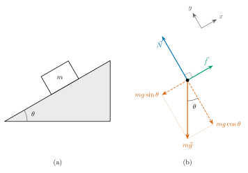
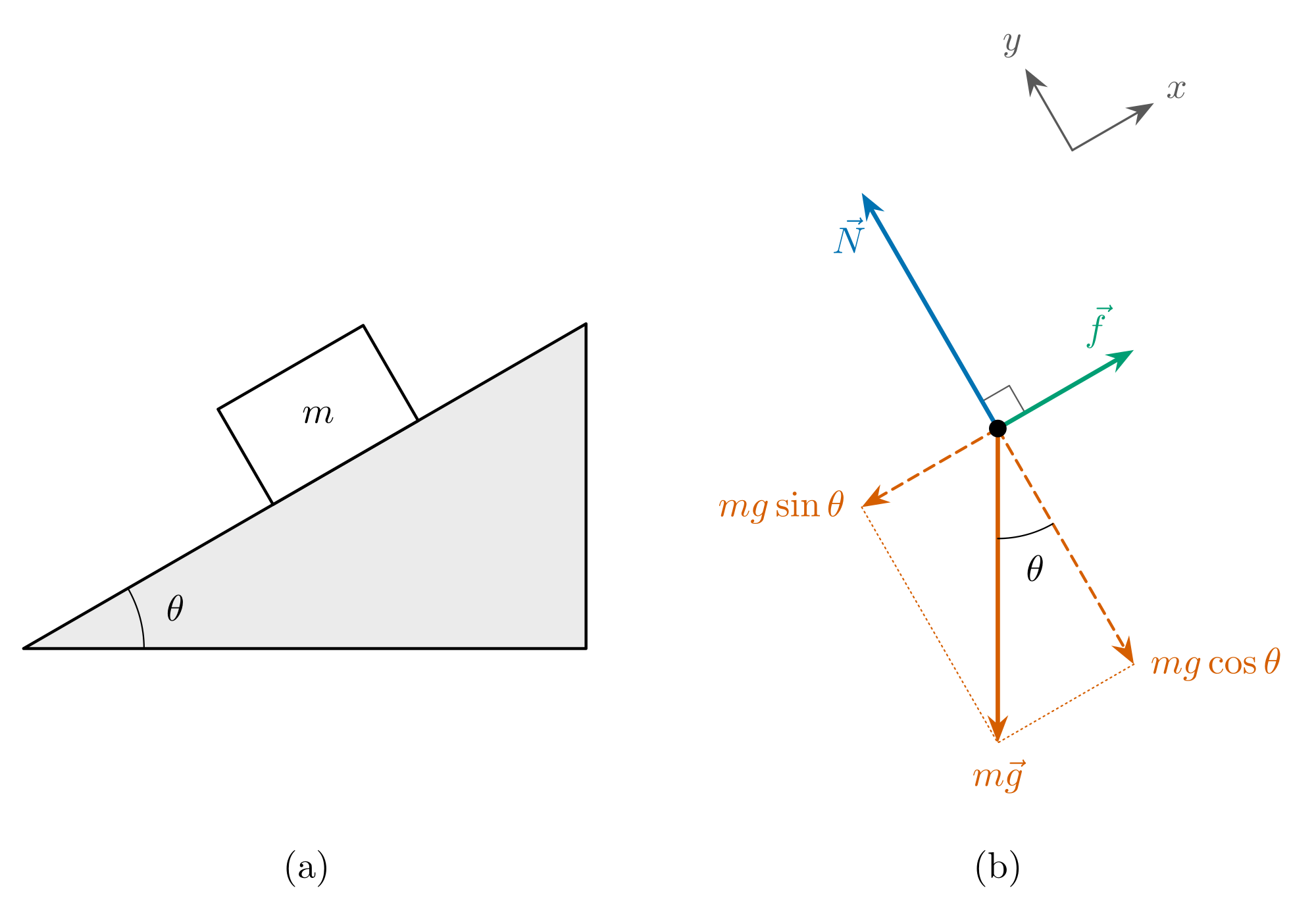
A free-body diagram shows one object on its own, with every force that acts on it drawn as an arrow from a single point. Here the object is a block at rest on a rough incline. Drawing (a) is the situation. Drawing (b) is its free-body diagram: the block has become a dot, the incline has gone, and three forces are left.
The arrows are drawn to scale for a 30° incline, so their lengths can be compared and they add up to zero, as they must for a block that is not accelerating. Switch to the blank version to practise labelling, or take the TikZ code further down and change the angle.
Parts and what they mean
| Part | What it shows |
|---|---|
| Weight, mg | The pull of gravity on the block. It points straight down, whatever the slope. |
| Normal force, N | The push of the surface on the block, at right angles to the surface. Here N = mg cos θ. |
| Friction, f | Along the surface, against the way the block would slide, so up the incline. The block is at rest, so this is static friction and f = mg sin θ. |
| mg sin θ | The part of the weight along the incline. Friction has to balance it. |
| mg cos θ | The part of the weight pressing into the incline. The normal force balances it. |
| The angle θ | The angle of the incline. It appears a second time, between the weight and the line at right angles to the surface. |
| The axes | x along the incline and y at right angles to it. Tilting them this way leaves only one force to split. |
Read the diagram as two balances
The block is at rest, so the forces balance along each axis separately. Along the incline: f − mg sin θ = 0, so f = mg sin θ. Across it: N − mg cos θ = 0, so N = mg cos θ. That is all of Newton's second law for this problem, read straight off the diagram.
The dashed arrows are not extra forces. They are the weight itself, redrawn as two parts that lie along the axes. Count the weight or its two parts, never both.
Tilt the incline further and mg sin θ grows while mg cos θ shrinks. The block starts to slide when mg sin θ is more than static friction can supply, which is μN at most. That happens once tan θ is greater than μ, the coefficient of static friction.
What a free-body diagram does not show
- Forces the block exerts on other things. The block pushes down on the incline, but that force acts on the incline, so it belongs on the incline's diagram.
- Velocity and acceleration. Only forces are drawn from the dot. If you want to show the acceleration, draw it beside the diagram.
- A net force arrow, or ma. The net force is the sum of the arrows already drawn, not one more of them.
- Where on the block each force acts. A dot is enough while the block does not tip or turn. For that you need the real points of contact.
- Other situations. With no friction there is no f. If the block slides down, friction is kinetic and still points up the incline. If it is pushed up the incline, friction points down it.
The TikZ code
This is the complete source of the diagram above. It compiles as it is with pdflatex, in LatexNotes, in Overleaf or on your own computer.
% Free-body diagram of a block at rest on a rough incline: (a) the situation, (b) the forces on the block.
% The forces are drawn to scale, so they add up to zero. Compiles as it is with pdflatex.
% Free to use and change: latexnotes.tech/diagrams/free-body-diagram
\documentclass[tikz,border=6pt]{standalone}
\usepackage{amsmath}
\usetikzlibrary{arrows.meta}

\definecolor{normal}{HTML}{0072B2}    % the normal force
\definecolor{friction}{HTML}{009E73}  % friction
\definecolor{weight}{HTML}{D55E00}    % the weight and its two parts

\newif\iflabels
\labelstrue   % write \labelsfalse here for the blank version to fill in

\newcommand{\slope}{30}   % the angle of the incline, in degrees
\newcommand{\W}{3}        % the length drawn for the weight mg, in cm

\begin{document}
\begin{tikzpicture}[>={Stealth[length=2.6mm]}, line cap=round, line join=round,
    force/.style={->, very thick}, part/.style={->, thick, densely dashed}]
  \pgfmathsetmacro{\N}{\W*cos(\slope)}   % normal force = mg cos(theta)
  \pgfmathsetmacro{\f}{\W*sin(\slope)}   % friction     = mg sin(theta)

  % (a) The situation: a block of mass m at rest on an incline at angle theta (its sloping side is 6.2 cm long)
  \begin{scope}[shift={(0,-1.75)}]
    \filldraw[thick, fill=black!8] (0,0) -- ({6.2*cos(\slope)},0) -- (\slope:6.2) -- cycle;
    \draw (1.15,0) arc (0:\slope:1.15);
    \begin{scope}[rotate=\slope]
      \filldraw[thick, fill=white] (2.75,0) rectangle (4.35,1.05);
      \iflabels \node at (3.55,0.525) {$m$}; \fi
    \end{scope}
    \iflabels \node at ({\slope/2}:1.5) {$\theta$}; \fi
  \end{scope}

  % (b) The free-body diagram: the block as a dot, and every force on it
  \begin{scope}[shift={(9.3,0.35)}]
    % The axes, drawn apart in the gap between the normal force and friction: x along the incline, y across it
    \begin{scope}[shift={(\slope+45:2.75)}, black!65]
      \draw[->, semithick] (0,0) -- (\slope:0.9);
      \draw[->, semithick] (0,0) -- (\slope+90:0.9);
      \iflabels
        \node at (\slope:1.15) {$x$};
        \node at (\slope+90:1.15) {$y$};
      \fi
    \end{scope}
    % The normal force is at right angles to the surface, and so to friction
    \draw[thin, black!65] (\slope:0.3) -- ++(\slope+90:0.3) -- (\slope+90:0.3);
    % The weight, straight down, and its parts along and across the incline
    \draw[weight, thin, densely dotted] (\slope+180:\f) -- (0,-\W) -- (\slope-90:\N);
    \draw[part, weight] (0,0) -- (\slope+180:\f);
    \draw[part, weight] (0,0) -- (\slope-90:\N);
    \draw[force, weight] (0,0) -- (0,-\W);
    % The normal force, away from the surface, and friction, up the incline
    \draw[force, normal] (0,0) -- (\slope+90:\N);
    \draw[force, friction] (0,0) -- (\slope:\f);
    % The incline's angle appears again between the weight and the line across the incline
    \draw (0,-1.05) arc (270:{270+\slope}:1.05);
    \fill (0,0) circle (2.4pt);
    \iflabels
      \node[normal, left=2pt] at (\slope+90:{0.82*\N}) {$\vec{N}$};
      \node[friction, above=3pt] at (\slope:{0.72*\f}) {$\vec{f}$};
      \node[weight, below=1pt] at (0,-\W) {$m\vec{g}$};
      \node[weight, left=1pt] at (\slope+180:\f) {$mg\sin\theta$};
      \node[weight, right=1pt] at (\slope-90:\N) {$mg\cos\theta$};
      \node at ({270+\slope/2}:1.38) {$\theta$};
    \fi
  \end{scope}

  \node at (2.7,-3.85) {(a)};
  \node at (9.3,-3.85) {(b)};
\end{tikzpicture}
\end{document}
\slopeis the angle of the incline in degrees. Change it and both drawings follow: the slope, the arrows and the two parts of the weight.\Wis the length drawn for the weight. The normal force and friction are worked out from it, so the arrows stay to scale.- For the blank version, change
\labelstrueto\labelsfalse. - On a smooth incline, delete the friction arrow and its label. The block then accelerates down the slope.
Drew your own diagram by hand?
LatexNotes turns a photo of your handwritten notes into LaTeX, and redraws hand-drawn graphs and diagrams as editable TikZ and pgfplots, like the code above.
Frequently asked questions
Why is the angle between the weight and the y axis also θ?
The weight is at right angles to the ground, and the y axis is at right angles to the incline. Turning two lines through the same 90° keeps the angle between them, so the angle between the weight and the y axis equals the angle between the ground and the incline.
Is the normal force always equal to mg?
No. It equals mg only on a level surface with no other vertical forces. On an incline it is mg cos θ, which is smaller, and it changes again if something pushes or pulls on the block at an angle.
Which way does friction point?
Along the surface, against the sliding, or against the sliding that would happen without it. A block left on an incline would slide down, so friction points up the incline.
Should I draw the components as well as the weight?
Draw the weight as a solid arrow and its components dashed, as here, or replace the weight with its two components. Never show all three as solid arrows: that counts gravity twice.
Can I use this diagram in my own notes?
Yes. Download the picture, or copy the TikZ code and change it as you like. It is free to use in notes, slides and worksheets.
References and further reading
- OpenStax, University Physics Volume 1, section 5.7: Drawing Free-Body Diagrams
- OpenStax, University Physics Volume 1, section 6.2: Friction