Shear force and bending moment diagram
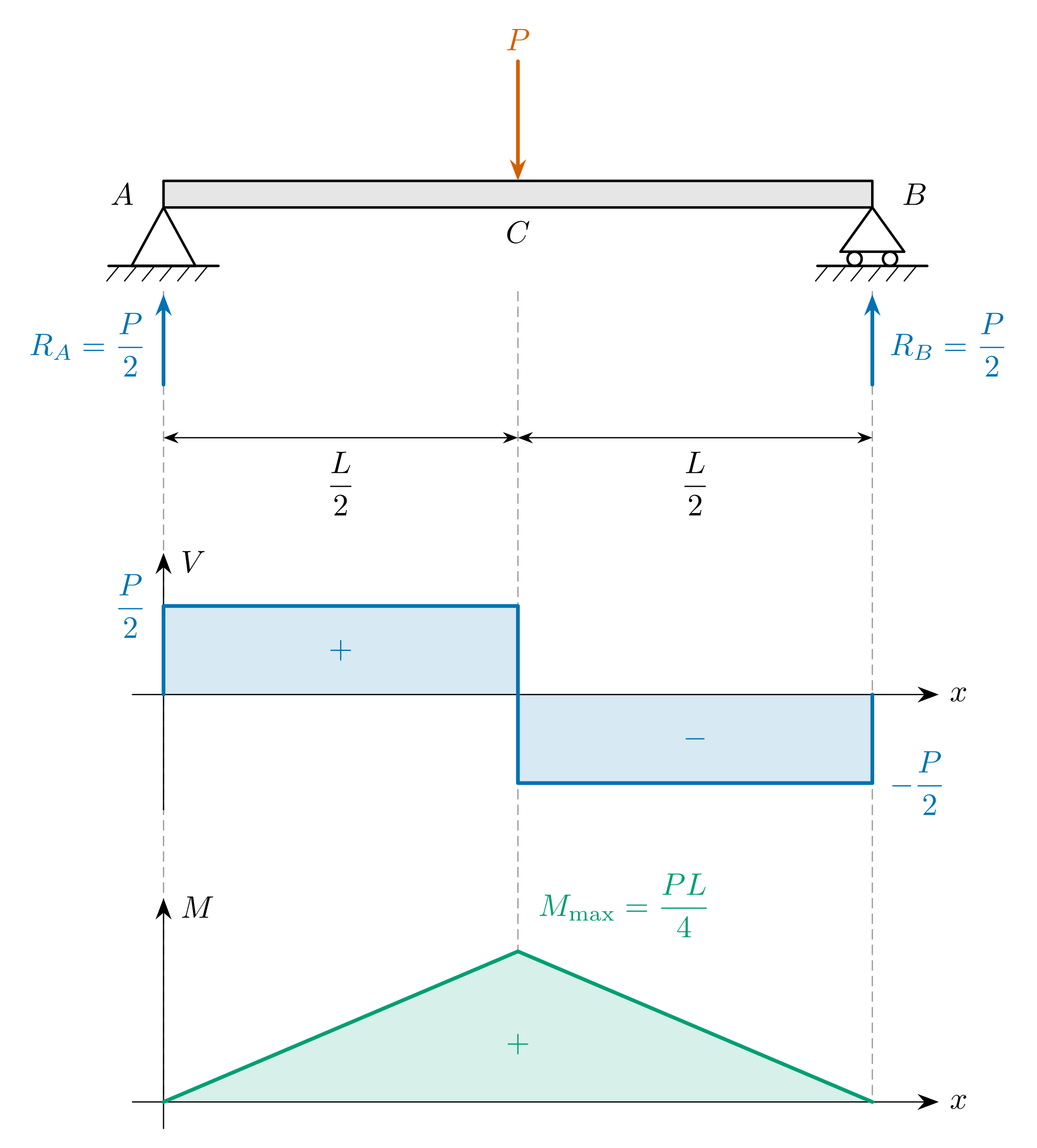
A shear force diagram and a bending moment diagram show how the internal forces in a beam change along its length. This is the case every course starts with: a beam of span L resting on a pin at A and a roller at B, carrying one load P at its middle, C.
The three drawings share one x axis, so you can read straight down the page: the load and the reactions at the top, the shear force V they cause, and the bending moment M that the shear builds up. Switch to the blank version to practise, or take the TikZ code further down and adapt it.
Parts and what they mean
| Part | What it shows |
|---|---|
| The beam | It spans L between the supports. Its own weight is left out. |
| Pin support, A | Holds the beam up and stops it moving sideways. |
| Roller support, B | Holds the beam up only, so its reaction is vertical. |
| Load P | A single point load at midspan, C. |
| The reactions | The upward forces from the supports at A and B. By symmetry each is P/2. |
| Shear force V | The internal force across the beam at x. It is +P/2 from A to C and −P/2 from C to B. |
| Bending moment M | The internal moment at x. It rises in a straight line from 0 at A to PL/4 at C, then falls back to 0 at B. |
Read the diagram from left to right
Start at A and walk along the beam. The reaction pushes the shear up to +P/2. Nothing else acts until the middle, so the shear stays level. At C the load pushes down, and the shear drops by exactly P, to −P/2. It stays there until the reaction at B brings it back to zero. A shear diagram that does not close at zero means the reactions are wrong.
The bending moment is the area under the shear diagram up to that point, because the shear is the slope of the moment. A level positive shear gives a moment that climbs in a straight line, and where the shear changes sign the moment peaks. The first rectangle has area P/2 × L/2 = PL/4, which is the greatest moment, under the load. The second rectangle is the same size and negative, so the moment returns to zero at B, as it must: a pin and a roller cannot hold a moment.
Three rules carry over to any beam:
- A point load makes a step in the shear diagram and a corner in the moment diagram.
- The slope of the moment diagram is the shear force.
- The moment is greatest where the shear crosses zero.
What the diagram does not show
- Other loads. A load spread evenly along the beam makes the shear a sloping line and the moment a parabola, with a greatest moment of wL²/8 on the same beam. The three rules still hold.
- Every book's sign convention. Here a sagging moment is positive and plotted above the axis. Many structural engineers plot the moment on the tension side of the beam instead, which turns this diagram upside down. The values do not change.
- Stress and deflection. The diagrams give the internal force and moment. The bending stress then comes from σ = My/I, and the deflection from the beam's stiffness, EI.
- The beam's own weight, and any force along the beam.
The TikZ code
This is the complete source of the diagram above. It compiles as it is with pdflatex, in LatexNotes, in Overleaf or on your own computer.
% Shear force and bending moment diagrams of a simply supported beam with a point load P at midspan.
% The three drawings share one x axis, so every feature lines up. Compiles as it is with pdflatex.
% Free to use and change: latexnotes.tech/diagrams/shear-force-bending-moment-diagram
\documentclass[tikz,border=6pt]{standalone}
\usepackage{amsmath}
\usetikzlibrary{arrows.meta,positioning}

\definecolor{load}{HTML}{D55E00}     % the applied load
\definecolor{shear}{HTML}{0072B2}    % the reactions and the shear force
\definecolor{moment}{HTML}{009E73}   % the bending moment

\newif\iflabels
\labelstrue   % write \labelsfalse here for the blank version to fill in

\newcommand{\Len}{8}       % the span L, as drawn, in cm
\newcommand{\Vh}{1.0}      % the height drawn for a shear force of P/2
\newcommand{\Mh}{1.7}      % the height drawn for a bending moment of PL/4
\newcommand{\Vzero}{-5.5}  % where the shear diagram's zero line sits
\newcommand{\Mzero}{-10.1} % where the moment diagram's zero line sits

\begin{document}
\begin{tikzpicture}[>={Stealth[length=2.4mm]}, line cap=round, line join=round]
  \pgfmathsetmacro{\mid}{\Len/2}

  % Lines down from the supports and the load, tying the three drawings together
  \foreach \x in {0,\Len}
    \draw[thin, densely dashed, black!40] (\x,-0.95) -- (\x,\Mzero);
  \draw[thin, densely dashed, black!40] (\mid,-0.95) -- (\mid,\Mzero+\Mh);

  % ---- The beam: a pin at A, a roller at B, the load P at midspan C ----
  \filldraw[thick, fill=black!10] (0,0) rectangle (\Len,0.3);
  % the pin (it holds the beam up and stops it sliding)
  \filldraw[thick, fill=white] (0,0) -- (-0.36,-0.66) -- (0.36,-0.66) -- cycle;
  % the roller (it only holds the beam up)
  \filldraw[thick, fill=white] (\Len,0) -- (\Len-0.36,-0.5) -- (\Len+0.36,-0.5) -- cycle;
  \foreach \dx in {-0.2,0.2} \filldraw[thick, fill=white] (\Len+\dx,-0.58) circle (0.08);
  % the ground under each support
  \foreach \x in {0,\Len} {
    \draw[thick] (\x-0.62,-0.66) -- (\x+0.62,-0.66);
    \foreach \i in {-0.5,-0.3,...,0.5} \draw (\x+\i,-0.66) -- ++(-0.14,-0.17);
  }
  % the load and the two reactions that balance it
  \draw[->, very thick, load] (\mid,1.65) -- (\mid,0.3);
  \draw[->, very thick, shear] (0,-2.0) -- (0,-0.98);
  \draw[->, very thick, shear] (\Len,-2.0) -- (\Len,-0.98);
  % the two half spans
  \draw[{Stealth[length=1.7mm]}-{Stealth[length=1.7mm]}, thin] (0,-2.6) -- (\mid,-2.6);
  \draw[{Stealth[length=1.7mm]}-{Stealth[length=1.7mm]}, thin] (\mid,-2.6) -- (\Len,-2.6);

  % ---- The shear force V: +P/2 up to the load, then it drops by P to -P/2 ----
  \fill[shear!16] (0,\Vzero) rectangle (\mid,\Vzero+\Vh);
  \fill[shear!16] (\mid,\Vzero) rectangle (\Len,\Vzero-\Vh);
  \draw[->, thin] (-0.35,\Vzero) -- (\Len+0.75,\Vzero);
  \draw[->, thin] (0,\Vzero-\Vh-0.3) -- (0,\Vzero+\Vh+0.6);
  \draw[very thick, shear] (0,\Vzero) -- (0,\Vzero+\Vh) -- (\mid,\Vzero+\Vh)
      -- (\mid,\Vzero-\Vh) -- (\Len,\Vzero-\Vh) -- (\Len,\Vzero);

  % ---- The bending moment M: a straight rise to PL/4 under the load, and back to zero ----
  \fill[moment!16] (0,\Mzero) -- (\mid,\Mzero+\Mh) -- (\Len,\Mzero) -- cycle;
  \draw[->, thin] (-0.35,\Mzero) -- (\Len+0.75,\Mzero);
  \draw[->, thin] (0,\Mzero-0.3) -- (0,\Mzero+\Mh+0.6);
  \draw[very thick, moment] (0,\Mzero) -- (\mid,\Mzero+\Mh) -- (\Len,\Mzero);

  \iflabels
    \node[above, load] at (\mid,1.65) {$P$};
    \node[left=6pt] at (0,0.15) {$A$};
    \node[right=6pt] at (\Len,0.15) {$B$};
    \node[below=1pt] at (\mid,0) {$C$};
    \node[left=2pt, shear] at (0,-1.55) {$R_A=\dfrac{P}{2}$};
    \node[right=2pt, shear] at (\Len,-1.55) {$R_B=\dfrac{P}{2}$};
    \node[below=1pt] at (\mid/2,-2.6) {$\dfrac{L}{2}$};
    \node[below=1pt] at (\mid*1.5,-2.6) {$\dfrac{L}{2}$};
    % shear
    \node[right=2pt] at (0,\Vzero+\Vh+0.5) {$V$};
    \node[right] at (\Len+0.75,\Vzero) {$x$};
    \node[left=2pt, shear] at (0,\Vzero+\Vh) {$\dfrac{P}{2}$};
    \node[right=2pt, shear] at (\Len,\Vzero-\Vh) {$-\dfrac{P}{2}$};
    \node[shear] at (\mid/2,\Vzero+\Vh/2) {$+$};
    \node[shear] at (\mid*1.5,\Vzero-\Vh/2) {$-$};
    % moment
    \node[right=2pt] at (0,\Mzero+\Mh+0.5) {$M$};
    \node[right] at (\Len+0.75,\Mzero) {$x$};
    \node[above right=1pt and 3pt, moment] at (\mid,\Mzero+\Mh) {$M_{\max}=\dfrac{PL}{4}$};
    \node[moment] at (\mid,\Mzero+\Mh/2.6) {$+$};
  \fi
\end{tikzpicture}
\end{document}
\Lenis the span as drawn, and\Vhand\Mhare the heights drawn for P/2 and PL/4.- The shear and moment shapes are drawn from their corner points, so another load case means changing those points and the labels.
- The colours of the load, the shear and the moment are the three
\definecolorlines at the top. - For the blank version, change
\labelstrueto\labelsfalse.
Drew your own diagram by hand?
LatexNotes turns a photo of your handwritten notes into LaTeX, and redraws hand-drawn graphs and diagrams as editable TikZ and pgfplots, like the code above.
Frequently asked questions
Why is the maximum bending moment PL/4?
Cut the beam at the middle and look at the left half. The only force on it is the reaction, P/2, acting a distance L/2 from the cut. The moment at the cut is P/2 × L/2, which is PL/4.
Where is the bending moment greatest?
Where the shear force is zero or changes sign, because the shear is the slope of the moment diagram. On this beam that is under the load.
Why does the shear force jump at the load?
A point load is treated as acting at a single point, so the shear changes by the whole of P across that point. A real load is spread over a short length, and the jump becomes a steep line.
Is a positive bending moment drawn above or below the axis?
Both are used. Mechanics textbooks usually plot a sagging moment as positive, above the axis, as here. Structural drawings often plot the moment on the tension side, which is below the axis for a sagging beam. Say which one you are using.
Can I use this diagram in my own notes?
Yes. Download the picture, or copy the TikZ code and change it as you like. It is free to use in notes, slides and worksheets.
References and further reading
- Baker and Haynes, Engineering Statics: Open and Interactive, section 8.4: Shear and Bending Moment Diagrams
- Baker and Haynes, Engineering Statics: Open and Interactive, section 8.5: Relations between Loading, Shear and Moment